
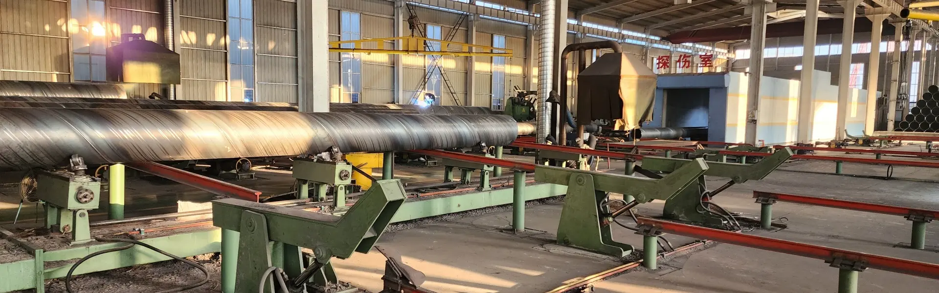
SSAW Spiral Welded Pipe Mill
In This Line
A spiral pipe mill from Tengtian is built in two classes: Φ219–820 mm with walls of 3–12 mm, and Φ219–1620 mm with walls of 5–16 mm. For straight-seam pipe up to Φ630 mm, see our large-diameter hfw tube mill; the api line pipe mill covers straight-seam line pipe with its own inspection chain; and the welded pipe guide sets out how the processes compare.
What Is a Spiral Pipe Mill?
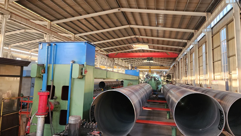
Diameter is changed by changing the forming angle — anywhere between 39° and 80° — so one machine covers its whole band rather than needing a line per size. A spiral pipe mill of the forward-swinging type is a complete line that turns coil into large-diameter welded pipe: uncoil, level, butt-weld coil to coil, prepare the strip edges, deliver and pre-bend, form helically over three rolls at a set angle, then weld inside and out by submerged arc and flying-cut to length.
 Changing Bore Without Changing RollsHow the 39°–80° forming angle is set, and what changes when the line moves to a new diameter.See the line →
 X-Ray, Hydrostatic and Ultrasonic, Station by StationThe finishing and inspection stations on each class, from weld repair to off-line ultrasonic testing.See the line →
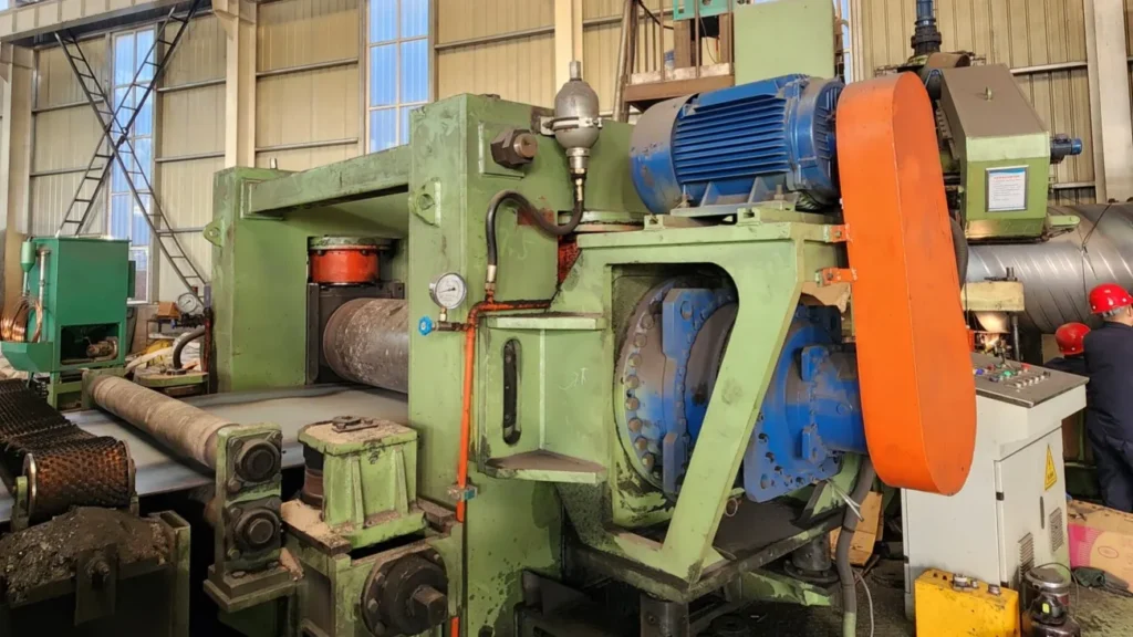 What the Large-Diameter Tier AddsWhat the Φ219–1620 mm class adds over the Φ219–820 mm class: edge milling instead of a disc shear, double outer welding, and off-line ultrasonic testing.See the line →
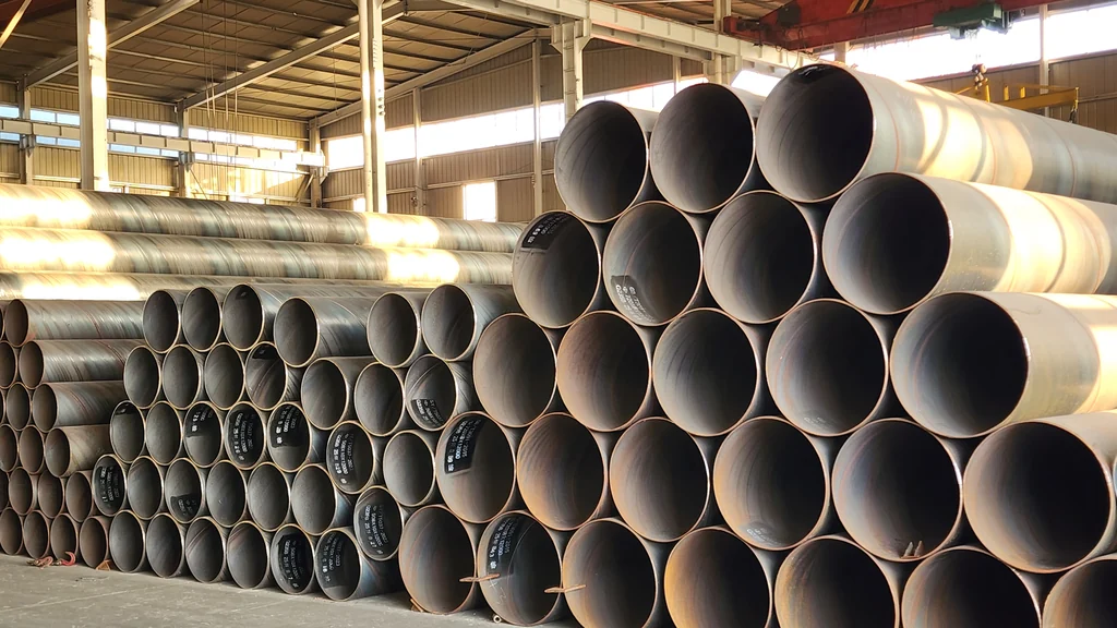 SSAW or HFWHow spiral submerged-arc and high-frequency straight-seam lines compare, and where each one fits.See the line →
Maximum pitch is 1250 mm on the Φ820 class and 1900 mm on the Φ1620 class. Our high-frequency straight-seam lines stop at Φ630 mm with the HG630; above that diameter, this spiral line is the one we build. Where both routes reach the same size, ssaw or hfw: how to choose sets out the difference, and the HG508 page covers the straight-seam side.
The line runs in nine stages:
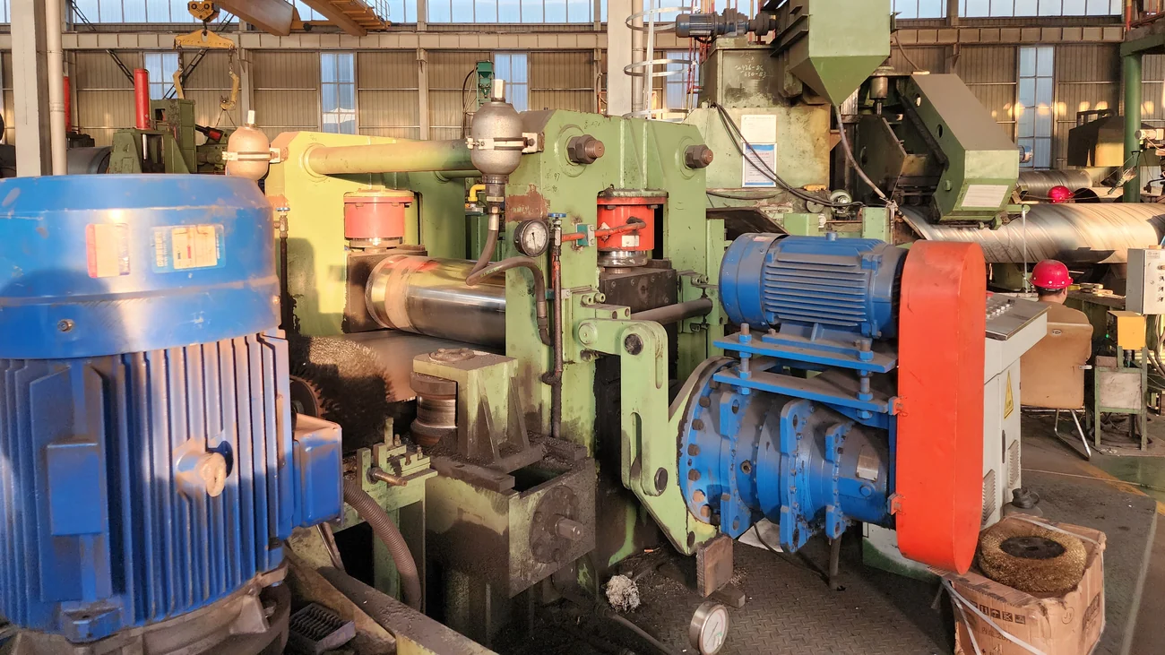
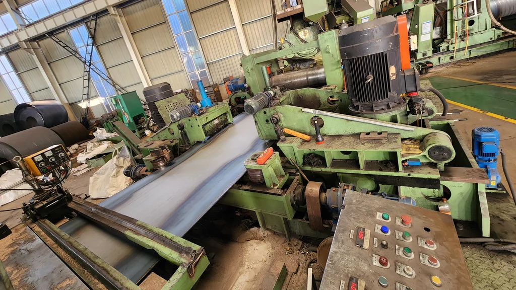
- Uncoiling (double-cone head) — a crane loads the coil, hydraulic cylinders raise the double cone heads into the coil bore, clamp it and centre it to the line, and an 11 kW main drive feeds strip into the leveller.
- Clamping and levelling — a five-roll leveller straightens the strip. Feed rolls Φ210 × 1350 mm, levelling rolls Φ190 × 1350 mm, 42CrMo hardened to HRC52-58. It can run actively in step with the delivery machine or passively with the clutch disengaged.
- Shear and butt welding — a hydraulic shear (Φ320 cylinder) trims the strip ends and a submerged-arc butt-welding trolley (MZ-2000, sharing the welding power source with the inner welder) joins coil to coil so production continues across coil changes.
- Edge preparation — the Φ1620 class mills both strip edges (Φ500 cutter head, 190 m/min, milling width 500–1250 mm, 2 × 22 kW, variable-frequency forward milling); the Φ820 class uses a disc shear instead.
- Delivery and guide-plate pre-bending — the delivery machine drives the whole line (planetary reducer, forged Φ360 42CrMo rolls, 2 × 15 kW), while guide plates with 42CrMo pre-bending rolls curve the strip edges before forming.
- Three-roll spiral forming — the strip enters at the set angle (39°–80°) and rolls 1# to 7# bend it into a spiral tube blank at the required diameter, with external sizing holding shape. The front bridge swings to set the angle.
- Inner and outer submerged-arc welding — inner and outer heads follow the spiral seam at 0.5–3 m/min. Flux is dried and magnetically separated before it covers the weld zone, and recovered afterwards.
- Flying cut-off and slag removal — a plasma cutting trolley (LGK-160 on the Φ820 class, LGK-200 on the Φ1620 class) cuts 8–12 m lengths while the mill keeps running; the pipe then passes a slag remover that cleans the inside seam.
- Finishing and inspection — on the Φ1620 class: slag removal, weld repair, pipe-end alignment, X-ray, hydrostatic test, off-line ultrasonic, end facing and bevelling. On the Φ820 class: weld repair, X-ray, end facing, hydrostatic test.
The mill is forward-swinging, centre-located and runs intermittently, forming by three-roll bending with external sizing.
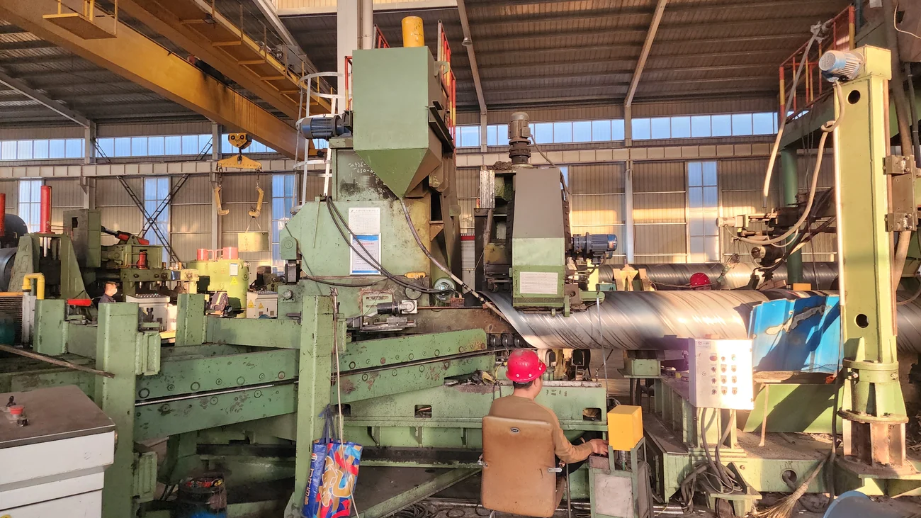
Range, Configuration and Output
Two classes: Φ219–820 mm × 3–12 mm, and Φ219–1620 mm × 5–16 mm.
Pipe length 8–12 m. Single-pipe weight up to 3 t on the Φ820 class and up to 7.5 t on the Φ1620 class.
Output. Roughly 62 tonnes per 8-hour shift on the Φ820 class, roughly 120 tonnes per 8-hour shift on the Φ1620 class.
Incoming strip is a stated requirement, not an assumption. Strip width 400–1050 mm (Φ820 class) or 500–1250 mm (Φ1620 class), width tolerance within ±5 mm; coil OD Φ1200–1800 mm / Φ1500–1800 mm, coil ID Φ600–760 mm / Φ508–610 mm, coil weight up to 15 t / 20 t.
Steel grade sets the wall-thickness ceiling. A capacity table gives the maximum wall for each diameter by grade. Grade is decided before wall thickness, not after.
The finished pipe is used for:
- oil and gas transmission pipelines
- low-pressure fluid, urban gas, and water supply and drainage pipelines
- industrial structural pipe
Key Parameters: Size Range, Wall Thickness, Line Speed and Welder Power Band
| Φ820 class | Φ1620 class | |
|---|---|---|
| Pipe OD × wall | Φ219–820 mm × 3–12 mm | Φ219–1620 mm × 5–16 mm |
| Pipe length | 8–12 m | 8–12 m |
| Single-pipe weight | up to 3 t | up to 7.5 t |
| Forming | Three-roll bending, external sizing, forming angle 39°–80° | same |
| Max pitch | 1250 mm | 1900 mm |
| Delivery speed | 0.5–3 m/min | 0.6–3 m/min |
| Welding speed | 0.5–3 m/min | 0.5–3 m/min |
| Submerged-arc arrangement | outer single / inner single | outer double / inner single |
| Main installed power | 200 kW incl. welder (160 kW in use) | 300 kW |
| Edge preparation | disc shear | edge miller (Φ500 cutter, 500–1250 mm, 2 × 22 kW) |
| Flying cut-off | plasma LGK-160 | plasma LGK-200 |
| Welding power source | domestic | Lincoln DC-1500 × 2 + AC-1250 |
| Operative standards | GB/T 9711, GB/T 5037 | GB/T 9711, API SPEC 5L |
| Output per 8-h shift | ≈ 62 t (1050 mm strip, 12 mm wall, Φ820, 12 m: about 21 pipes of 3 t) | ≈ 120 t (1250 mm strip, 16 mm wall, Φ1620, 12 m: about 15 pipes of 7.5 t) |
| Manufacturing lead time | 120 days | 150 days |
| Coil outside / inside diameter | Φ1200–1800 / Φ600–760 mm | Φ1500–1800 / Φ508–610 mm |
| Strip width | 400–1050 mm, tolerance ±5 mm | 500–1250 mm, tolerance ±5 mm |
| Coil weight | up to 15 t | up to 20 t |
| Overhead crane | 20/10 t + 5 t | 32/16 t + 10 t |
| Crane hook height | at least 7 m | at least 6.5 m |
| Workshop | 32 × 18 m | 36 × 24 m; overall layout 150 × 24 m |
Key roll materials: forming rolls GCr15 hardened to HRC56-60; feed, levelling and pre-bending rolls 42CrMo at HRC52-58; delivery rolls forged 42CrMo.
Key bought-in components on the Φ1620 class are listed by brand so a buyer can price and check them independently: Lincoln welding power sources, Siemens PLC and motors, Delta drives, Schneider (partly CHINT) electrical components, Jiangsu Guomao cycloidal reducers, Jiangsu Tongli planetary reducers, Harbin or Wafangdian bearings, Beijing Huade hydraulic valves.
Maximum Wall Thickness by Pipe Diameter and Steel Grade
Φ1620 class (mm):
| Pipe diameter | Q235B | Q355C | L360 |
|---|---|---|---|
| Φ219 | 7 | 6 | 6 |
| Φ273 | 8 | 6 | 6 |
| Φ325 | 9 | 8 | 8 |
| Φ426 | 9.5 | 8 | 8 |
| Φ508 | 10 | 8.5 | 8.5 |
| Φ630 | 12 | 9.5 | 9.5 |
| Φ820 | 12.7 | 10 | 10 |
| Φ1020 | 14 | 12 | 12 |
| Φ1220 | 14 | 12 | 12 |
| Φ1420 | 16 | 14 | 14 |
| Φ1620 | — | 16 | 16 |
Φ820 class (mm):
| Pipe diameter | Q235 | Q355B | L360 |
|---|---|---|---|
| Φ219 | 7 | 6 | 6 |
| Φ273 | 8 | 7 | 7 |
| Φ325 | 10 | 8 | 7 |
| Φ426 | 10 | 8 | 7 |
| Φ529 | 10 | 9 | 8 |
| Φ630 | 11.5 | 9.5 | 9 |
| Φ720 | 12 | 10 | 10 |
| Φ820 | 12 | 11.5 | 10 |
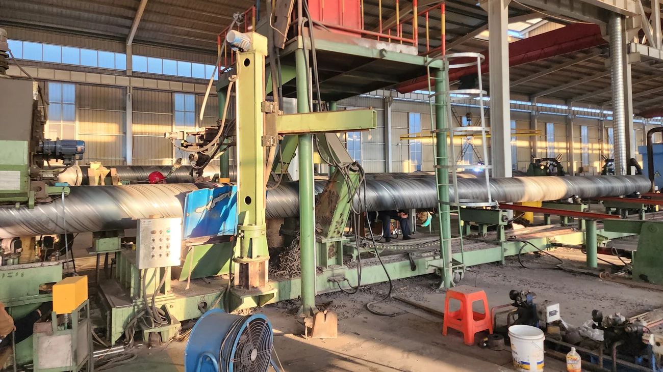
How to Choose the Right Model
Anything above Φ820 mm requires the Φ1620 class outright. Three inputs decide the class: the largest outside diameter to be sold, the heaviest wall at that diameter, and the steel grade it will be made from.
Diameter first. Below it, both classes reach the diameter and the decision moves to wall and grade — the Φ820 class stops at 12 mm wall, the Φ1620 class carries to 16 mm.
Then the inspection requirement, which is often what actually decides it. If the finished pipe must be certifiable to API SPEC 5L, that is the Φ1620 class — the Φ820 class is built against GB/T 9711 and GB/T 5037. The stations that carry each pipe through X-ray, hydrostatic and ultrasonic testing are set out in the ssaw inspection chain, and what the Φ1620 class adds is on the large-diameter ssaw line page.
Then the plant itself, because a spiral line has real building requirements: workshop 32 × 18 m with a 20 t crane at 7 m hook height for the Φ820 class; 36 × 24 m with a 32 t crane at 6.5 m for the Φ1620 class. Supply 220 / 380 V 50 Hz, compressed air 0.6 MPa. Feed direction can be set left or right to suit an existing workshop.
Scope of Supply, Installation and Commissioning
Lines are quoted ex-works (EXW); the buyer books and pays the freight. On the Φ1620 class the finishing section includes a 1200-tonne hydrostatic testing machine, 195 sets of test-bay bases, 47 sets of driven roller tables and 45 sets of idle roller tables with 45 suction units.
Installation and commissioning are guided on site by our engineers, with online support behind them; the buyer provides the installation crew and covers the engineers’ travel, lodging and daily allowance. Our engineers also train the operators. Rolls and key wear parts are machined at the works on its own CNC equipment, which is what makes continuous roll supply possible years after handover.
The line is accepted on continuous production of two different pipe sizes.
Certifications: ISO 9001:2015 quality management system; CE marked under the EC Machinery Directive 2006/42/EC.
Line Photos from the Works
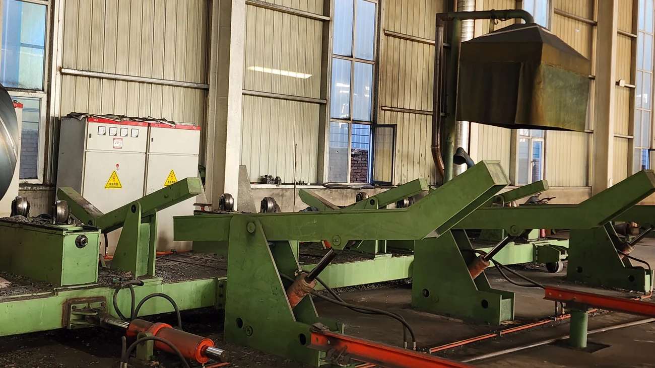
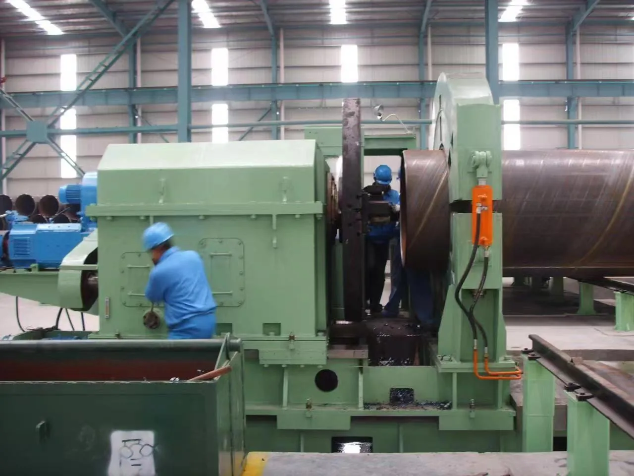
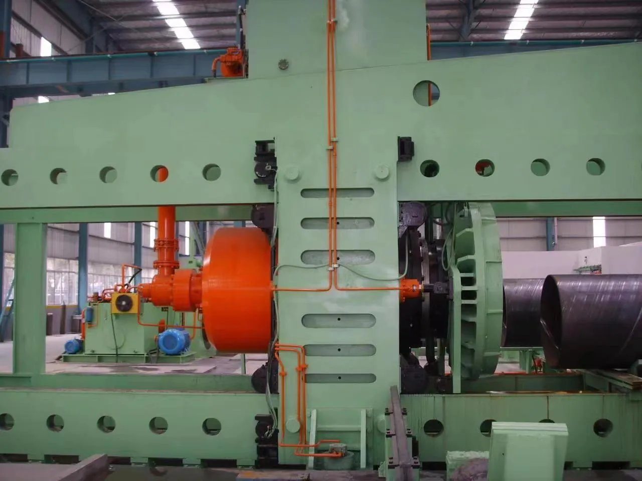
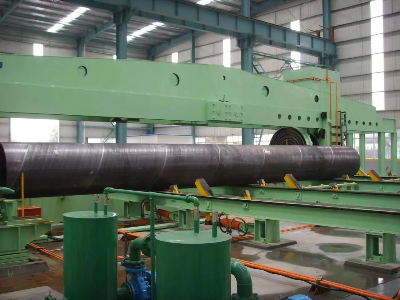
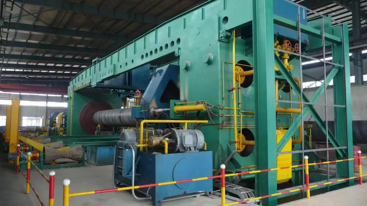
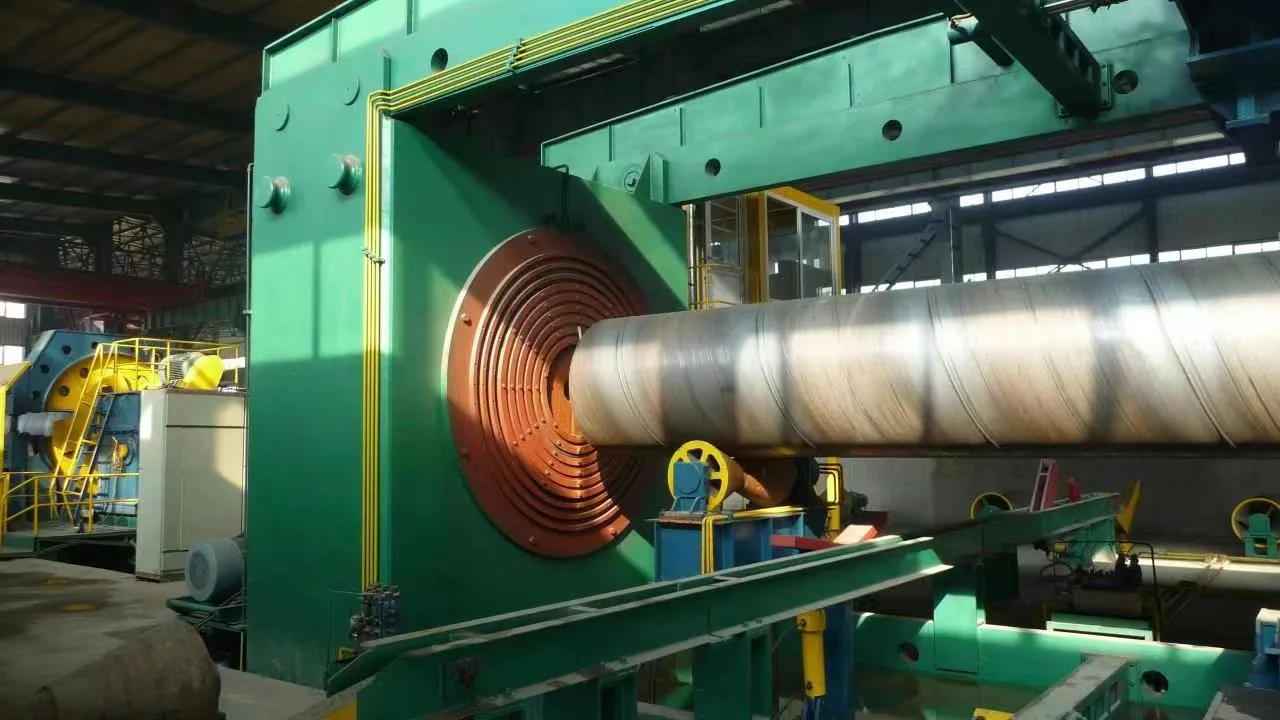
Five photographs of this line, taken in our own workshop. Click any photo for the full-size image.
More from this line
More on this line — specifications, model steps and photographs.
 Small Diameter Tube Mill
 Steel Coil Slitting Line
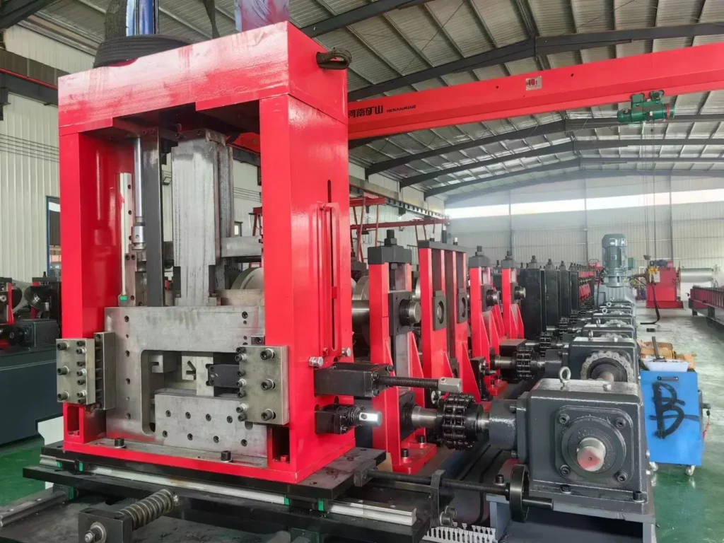 Roll Forming Machine
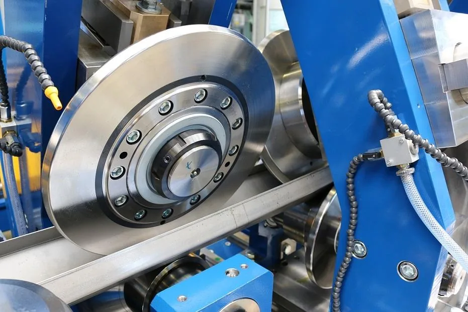 Purlin Machine Lines
Send Your Enquiry
Tell us the pipe outside-diameter range, the wall thickness and the output you need. An engineer reads every enquiry — it does not land in a general sales inbox.