Home › SSAW Spiral Welded Pipe Mill › Changing Bore Without Changing Rolls
On a spiral line the pipe diameter is set by the forming angle, not by the rolls.
In This Line
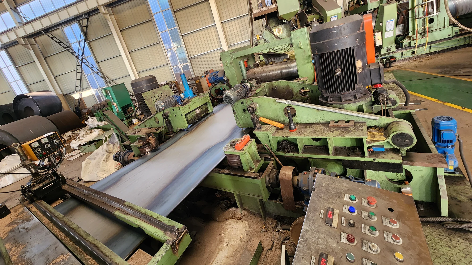
The angle range is 39 to 80 degrees, set by swinging the front bridge, and a diameter change on this line does not require a change of forming rolls.
The Numbers That Set a Size on This Line
- Forming angle range: 39° to 80°, set by swinging the front bridge.
- Maximum pitch: 1250 mm on the Φ820 grade, 1900 mm on the Φ1620 grade.
- Incoming strip width: 400–1050 mm or 500–1250 mm, with width tolerance within ±5 mm.
- A diameter change does not require changing the forming rolls.
- Pipe envelope: Φ219–820 mm × 3–12 mm (up to 3 t per pipe) or Φ219–1620 mm × 5–16 mm (up to 7.5 t per pipe), 8–12 m long.
What Is Forming Angle 39°–80°
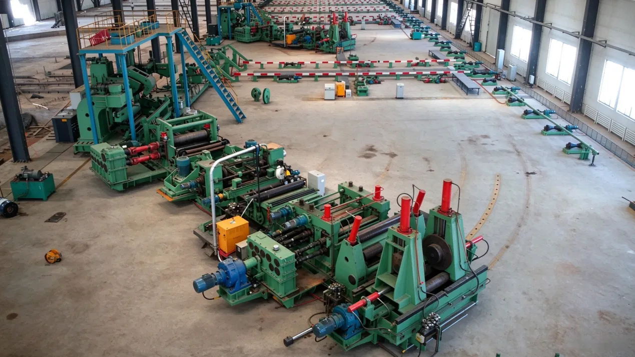
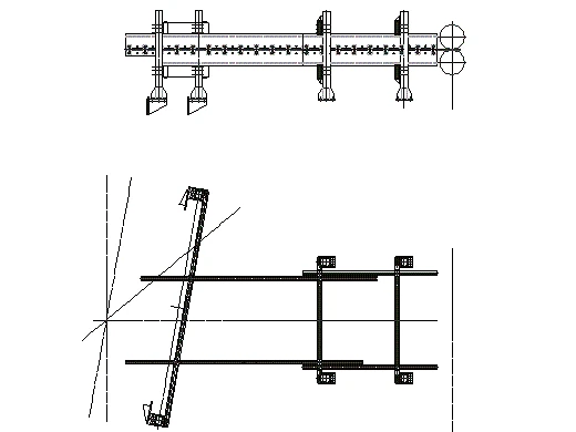
In operation, strip is fed in at a set forming angle between 39 and 80 degrees, is force-bent over three rolls and wound along a helix, and its two edges meet on the blank to form the spiral seam. The forming angle is the angle at which the strip enters the forming machine relative to the axis of the pipe being wound. External sizing then holds the shape.
The spiral mill forming angle and the strip width together determine the pipe diameter, and the pitch follows from both.
In practice, a size change on this line is made by resetting the forming angle, so one spiral line covers Φ219 to Φ1620 mm rather than one line per diameter band. Where this line sits against our high-frequency straight-seam range is set out on the ssaw spiral welded pipe mill page.
The trade-off is a welding speed of 0.5 to 3 metres per minute and intermittent production; how that compares with straight-seam lines is covered in ssaw vs hfw pipe mill.
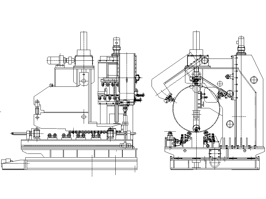
Three roll bending spiral pipe mill
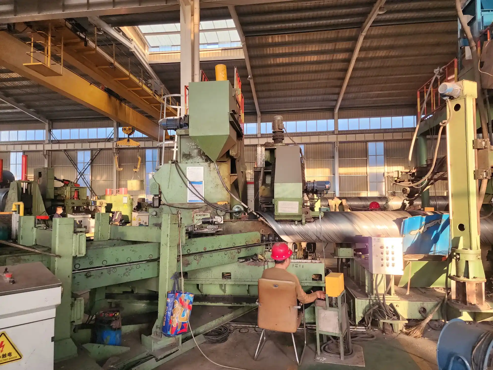
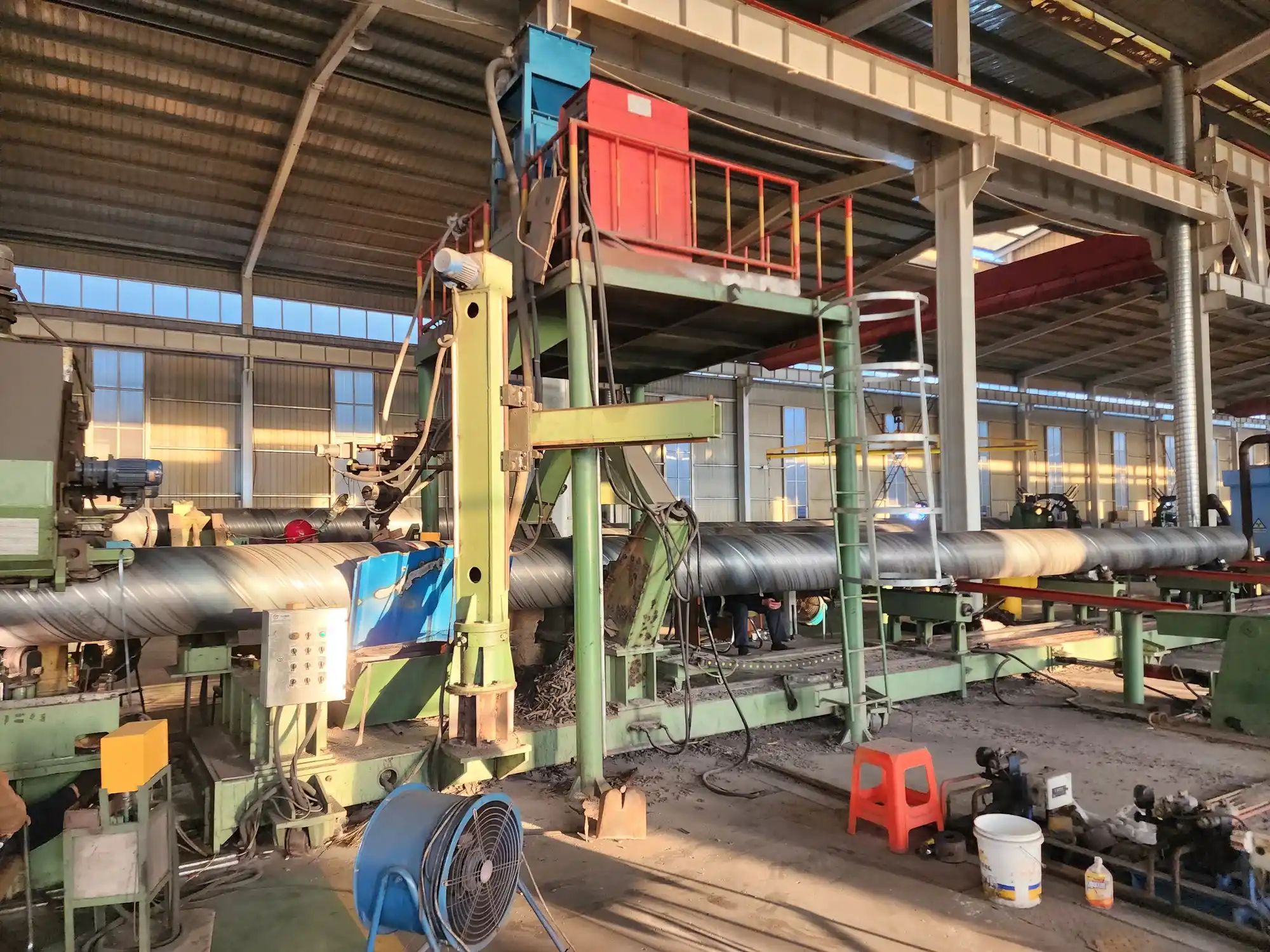
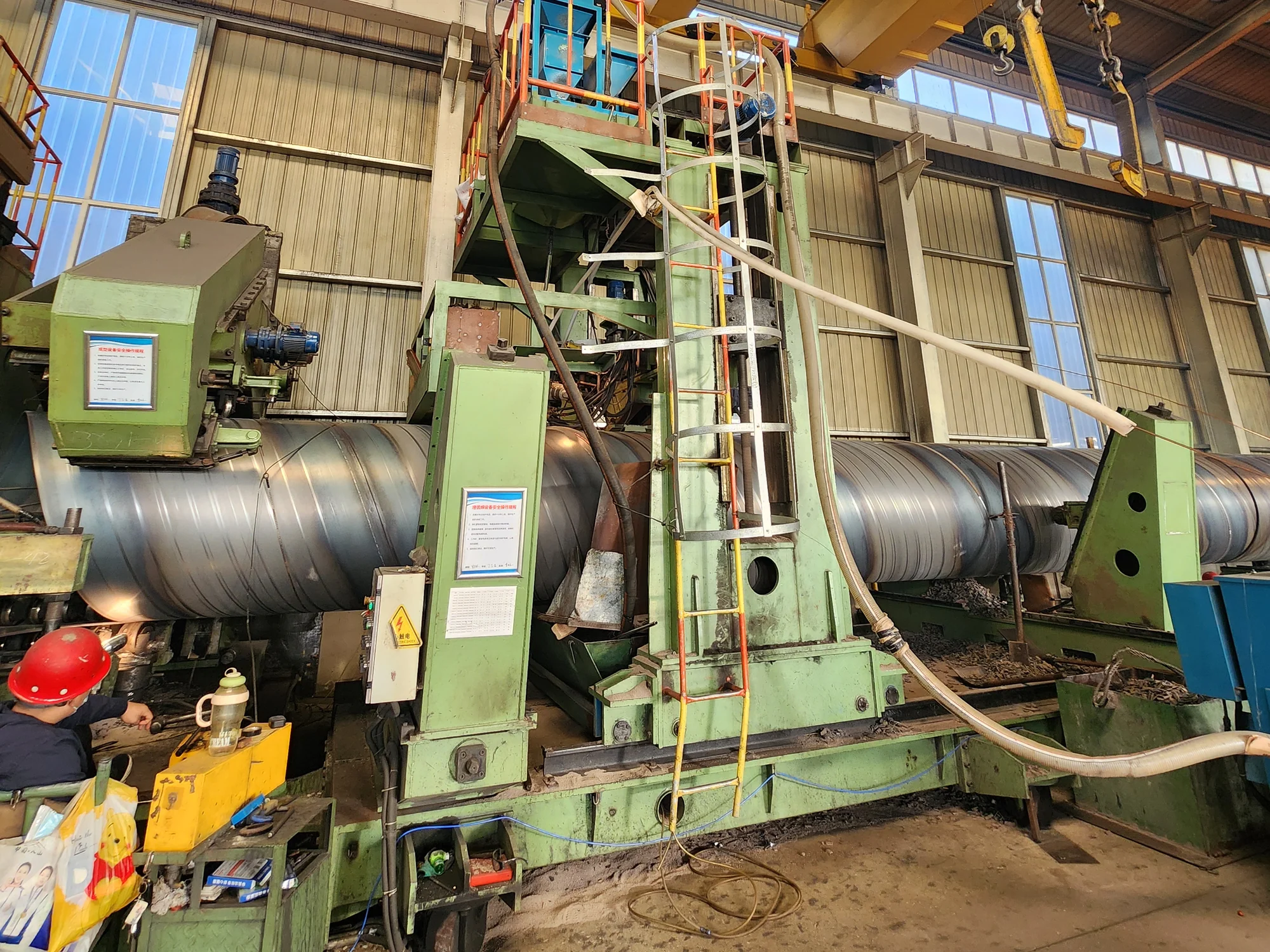
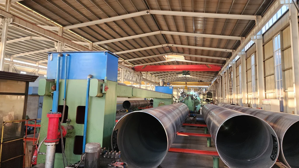
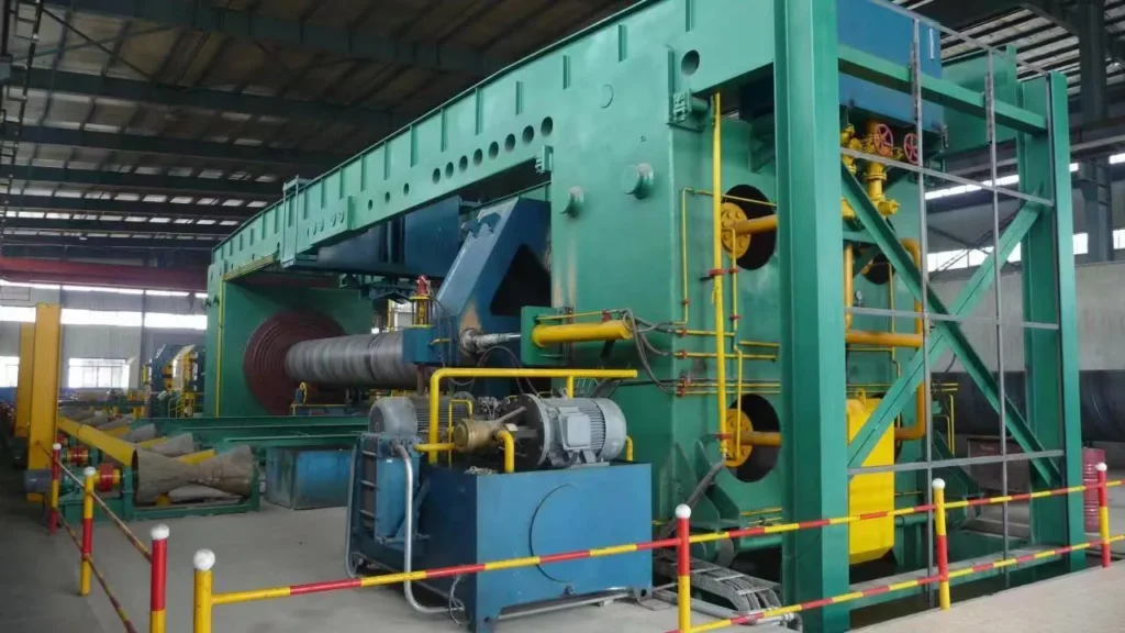
The forming machine bends the strip over three rolls with external sizing to produce the spiral blank. A front bridge carries the equipment ahead of forming and swings to set the forming angle; a rear bridge carries the equipment after forming, allows fine angle adjustment, and discharges the pipe.
The build includes a twin base with an inclination, forming rolls 1# to 7# in GCr15 hardened to HRC 56–60 on Φ130 bearing rollers, and a front-bridge swing cylinder of Φ150 / Φ85 × 450.
Forming Angle 39°–80° — Method and Measured Values
The angle range is 39 to 80 degrees, and four limits bound the size-change operation. Maximum pitch is per line grade: 1250 mm on the Φ820 grade and 1900 mm on the Φ1620 grade.
Incoming strip width is 400 to 1050 mm or 500 to 1250 mm depending on grade, with a stated incoming requirement that width tolerance stays within ±5 mm. And the resulting pipe envelope is Φ219 to Φ1620 mm at 5 to 16 mm wall.
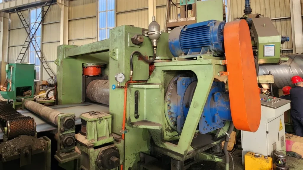
Two further mechanisms hold the shape once the angle is set. Guide plates with 42CrMo pre-bending rolls hardened to HRC 52–58 curve the strip edges before they enter the forming machine.
And the delivery machine — a planetary reducer driving Φ360 forged 42CrMo rolls through 2 × 15 kW variable-frequency motors at 0.6 to 3 metres per minute on the Φ1620 grade — is the line’s main drive.
Standards Behind the Forming-Angle Figures
The standards for this line apply to the finished pipe rather than to the forming operation. Pipe from both grades is made to GB/T 9711; the Φ820 grade also lists GB/T 5037, and the Φ1620 grade also lists API 5L. More on the first is in gb/t 9711 for spiral welded line pipe.
Step-by-Step Procedure
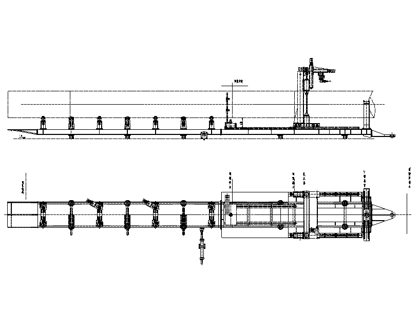
Loading and threading the coil works as follows: the crane lifts the coil to the uncoiler centre, the twin cone heads align and clamp hydraulically and centre the coil to the machine axis, a swing knife head presses the strip down, and the main drive then leads the strip head into the pinch-and-levelling unit.
Setting a new outside diameter means adjusting the front-bridge swing angle, with fine adjustment on the rear bridge, to set the forming angle; determining the pitch together with the strip width; and re-checking the machine’s centre positioning. After the change, the swing-angle setting and the centre positioning are checked again, and the actual diameter and pitch are measured on the first pipe.
The operation requires trained set-up personnel.
Coil Joining and Welding Set-Up
Joining coils is shearing the head and tail square with the hydraulic shear, submerged-arc butt welding them on a travelling welding carriage, and re-centring with powered or manual vertical rolls before feeding resumes.
Setting the welding parameters needs process training: flux is loaded and dried and the wire spool fitted, and inner and outer welding current, voltage and speed are set, with welding at 0.5 to 3 metres per minute.
Ssaw mill installation and commissioning
Installation and commissioning are guided on site by our engineers; the commissioning team includes a set-up technician who adjusts the forming section for each pipe size, our engineers train the operators, and the line is accepted when two different pipe sizes run continuously.
The Forming-Angle Envelope
The envelope is defined by these limits: the angle runs from 39 to 80 degrees, the pitch is capped at 1250 mm on one grade and 1900 mm on the other, incoming strip runs 400 to 1050 mm or 500 to 1250 mm wide within ±5 mm, and the pipe that comes out is Φ219 to Φ1620 mm at 5 to 16 mm wall, 8 to 12 metres long, up to 7.5 tonnes.
For your sizes, the actual diameter and pitch are measured on the first pipe after set-up, and wall thickness, line speed and shift output are confirmed against your pipe size, material grade and cut length at quotation.
The capacity figures that go with the envelope apply to the line as a whole, not to any single angle setting. Installed main-machine power is 200 kW on the Φ820 grade, with an actual draw of 160 kW, and 300 kW on the Φ1620 grade.
Delivery speed is 0.5 on the Φ820 grade or 0.6 on the Φ1620 grade up to 3 metres per minute, and welding speed is 0.5 to 3 metres per minute.
What feeds the forming machine
Three stages sit upstream of the forming angle and each one can move the result. Uncoiling runs on a twin-cone-head uncoiler that lifts, aligns and clamps hydraulically and centres the coil to the machine axis. Pinch-and-levelling follows.
On the Φ1620 grade an edge milling machine mills both strip edges, with a Φ500 cutter head, a maximum cutter speed of 190 metres per minute and a milling width of 500 to 1250 mm; on the Φ820 grade the equivalent stage is disc shearing of the edges.
That matters for size changes because the edge preparation and the pre-bend together decide whether the two strip edges meet cleanly once the angle has been reset.
What to ask the factory for
Three questions turn a general enquiry into a specification. Ask for the forming angle and pitch actually used for the two or three diameters you intend to run, measured on the first pipe rather than taken from a design chart.
Ask which incoming strip widths the quotation assumes, because the width is half of what sets the diameter and the ±5 mm tolerance is a stated incoming requirement. And ask how long a size change takes on the shop floor with your own crew.
Resource Downloads
From the Workshop
 SSAW or HFW
 What the Large-Diameter Tier Adds
 X-Ray, Hydrostatic and Ultrasonic, Station by Station
 GB/T 9711 for Spiral Welded Line Pipe
Send Your Enquiry
Tell us the pipe outside-diameter range, the wall thickness and the output you need. An engineer reads every enquiry — it does not land in a general sales inbox.